
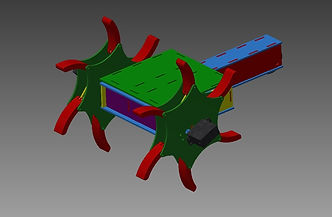
Firstly we started working on the design. Using Inventor 2013 we started from a basic unit box that would contain our electronics, driving axels, motors etc. In the first version the box and tail were designed to be one piece. The body of the robot would be driven and supported by two wheels on the side, each driven by a 12 V DC motor.
The unique thing about our design was the wheel mechanics. Each wheel was designed to consist of 6 legs, each connected to 2 beams which were attached to a central plate. Using a servo motor we wanted to rotate the central plate, which would pull the beams and thus the legs of the wheel in an open position This made both designing and building these wheels very complex and time consuming.
The benefit of using these wheels would have been that driving on the ground would have been possible in a normal fashion, with closed round wheels. While we could open up the wheels to climb the stairs. This would result in a smooth fast ride with closed wheels and a fast efficient climb.
Mechanical Design

Electronic Design
The strength of our robot is its simplicity and the electronic design is the perfect example of this. Since we do not have any lifting systems or sensors since we do not require them, our electronic design is solely based on driving the robot. This was accomplished by creating one PCB plate.

Of course we encountered many difficulties and problems with the first version of our robot. For starters our reduction generated by our gears was not big enough to generate sufficient torque to pull the weight of the robot. We also struggled with the incline of the stairs. It seemed as if the robot was not long enough resulting in a very steep incline once he got up the first staircase. Which in turn resulted in the fact that the robot had a tendency to fall backwards down the stairs.
Problems
All the problems mentioned above had to be addressed with proper solutions. We decided that the problems were to fundamental to just repair them so we decided to make a whole new version and start from scratch.
We made the gears larger so we got a bigger reduction, resulting in enough torque to pull the robot up the stairs.We also changed the design of the body. The body was made larger to make some room for the bigger gears. The tail was also removed from the body. We opted to use an aluminum beam screwed to the bottom as the tail of our robot. The advantages of an aluminum tail over the mdf tail are clear: stronger, lightweight and smaller.
Solutions
